Project 9 · Civil and mechanical engineering
When the textbook beam formula breaks
Every engineering student learns this formula. Find out exactly when it stops being true.
- Math
- Algebra II
- You need
- Rulers, coins and a clamp
- Tools
- Rulers, coins, clamp, Python or a spreadsheet
- Solver
- Linear elasticity, 3D
The question
The classic beam formula is taught as fact, but it assumes a long, slender beam. How short can a beam be before the formula is wrong by 5%, and does the material's Poisson ratio change that?
Objectives
Twelve weeks, in the four stages every TopEdu project follows. Your mentor reviews each checkpoint before you move on.
Weeks 1 to 3
Learn to trust the model
Run 09_cantilever_beam.py until its CHECK line says PASS, and explain every line of it to your mentor. Then reproduce a known answer: A slender beam's tip sag should approach 3ρgL⁴ / (2Eh²). Our test runs give 0.996 of that at length/depth 14 and 1.073 at 3.
Checkpoint: you reproduce a known answer and report how close you got.
Weeks 4 and 5
Ask your own question
Narrow the question above to one sentence that could turn out to be wrong, and write your prediction before you run anything. The first experiments below are a place to start.
Checkpoint: a one-page plan with your question and prediction.
Weeks 6 to 9
Run it, then measure the world
Simulate a square-section beam fixed at one end, sagging under its own weight, while shortening it step by step, and map the error of the formula. Then step away from the screen: clamp rulers or strips at different lengths to a desk, load them with coins, and measure the sag.
Checkpoint: one chart comparing your model with reality.
Weeks 10 to 12
Explain the gap, and share it
Work out why your model and your measurements disagree, test at least one explanation, and write it up yourself. Say which numbers came from the starter and which from the lab. Keep the honest limit in view: the clamped end has a stress singularity, so results near it depend on the grid. Report grid sensitivity; this is a study and not a design tool.
Checkpoint: a final paper, your code and a ten-minute talk.
The data
What the lab lets you change, how the project was checked before we listed it, and what the starter prints on a laptop.
Settings in the online lab
| Setting | Range | Starts at |
|---|---|---|
| Length / depth | 2 to 14 ratio | 10 |
| Poisson ratio | 0.05 to 0.4 | 0.3 |
Checked on the research solver
| Solver (Linear elasticity, 3D) | L/h 14: sag/formula 0.996 (1066 iterations, 47.2 s); L/h 10: sag/formula 0.998 (737 iterations, 22.7 s); L/h 5: sag/formula 1.017 (433 iterations, 8.8 s); L/h 3: sag/formula 1.073 (313 iterations, 5.5 s) |
|---|---|
| Known answer | with shear 1.005; with shear 1.010; with shear 1.042; with shear 1.116 |
| Error | 3.77% (limit 8.00%): passed |
| A first finding | the formula is close for long beams and increasingly wrong for short ones, which is the project's question |
What the starter prints
From the run that built this page. Timings depend on your computer; the CHECK line must say PASS.
beam equation: tip sag 0.12500, formula 0.12500, error 0.003%
CHECK numerical beam against q L^4 / (8 E I) -> PASS (limit 1%)
tip sag / textbook formula, by length / depth:
  L/h   Timoshenko   lab 3D (our test)
   14   1.005        0.996
   10   1.010        0.998
    5   1.042        1.017
    3   1.116        1.073
Timoshenko says the textbook formula is 5% low once L/h < 4.6; does the 3D solver agree?
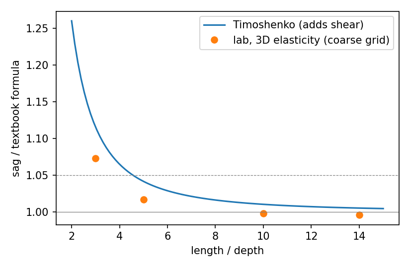
The starter code
One Python file that needs only numpy and matplotlib. Run python3 09_cantilever_beam.py --show to see the plots. How to set up.
The model
A beam fixed at one end sags under its own weight. The textbook (Euler-Bernoulli) answer for the tip sag is w = q L^4 / (8 E I) with q = weight per length, E the stiffness of the material, I = h^4 / 12 for a square. It assumes a long, slender beam. A short beam also bends by shear, which the formula leaves out. Timoshenko's theory adds it: w = q L^4 / (8 E I) + q L^2 / (2 kappa G A), with G = E / (2 (1 + nu)) and kappa = 5/6.
The full 3D answer needs the online lab (elasticity in 3D is too heavy for a starter). This file does the parts you can do on a laptop:
What it does
- Stage 1: solve the beam equation E I w'''' = q numerically and check it against the formula. CHECK should say PASS.
- Then it compares both theories with the lab's 3D results that we measured when we tested this project.
- Stage 2: measure real rulers, fit the L^4 law, and find where the formula stops working.
Your first experiments
From the YOUR TURN list at the bottom of the file. Write your prediction in your log before you run each one.
- Rulers: clamp a ruler to a desk with 10, 15, 20, 25 and 30 cm hanging over, measure the tip sag, and save a CSV with columns length_cm,sag_mm. Run: python 09_cantilever_beam.py my_rulers.csv Predict the power first. Coins at the tip change it: why?
- From your fit, work out E for the ruler (weigh it to get q). Compare with a published value for the material.
- In the online lab, rerun the 3D beam at L/h = 3 and 5 with a finer grid. How much do the numbers above move? The clamped end has a stress singularity, so report how your answer depends on the grid.
- Change nu to 0.05 and 0.4. Does the 5% threshold move? Check one value in the lab.
Download 09_cantilever_beam.pyAll ten (.zip)Instructions (PDF)
The real world
Clamp rulers or strips at different lengths to a desk, load them with coins, and measure the sag.
The honest limit
The clamped end has a stress singularity, so results near it depend on the grid. Report grid sensitivity; this is a study and not a design tool.
Want to work on this one?
Members run it on the research solver in the lab and choose a mentor to guide them.